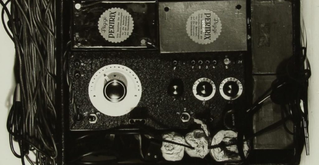
Over the last few months, I’ve gotten a crash course in spy radios. Thomas Hoeppe, an amateur Ham radio operator, and a crafter of replica Abwehr spy radio sets, has been answering my many and varied questions on the finer details of spy radios.
Naturally, I am most intrigued by the radios brought by the LENA spies, particularly my grandfather, Josef Jakobs. I had thought that he had an SE 88/5 radio with him but, after Thomas pored over various radio schematics, I learned that Josef had an SE 92/3. The differences are detailed in my earlier blog which I ended by comparing the S88/5 of Waldberg and Meier with the SE 92/3 of Walti and Ter Braak.
I had added some coloured circles, highlighting various features of the transmitter portion of those three sets. In doing so, I realized that the functions of the other knobs, dials and sockets were a complete mystery to me. I decided to create an annotated diagram of the front panels of the SE 88/5 (receiver and transmitter portions) and the SE 92/3. With Thomas’s help, I hope that I’ve created something helpful for the spy radio novice.
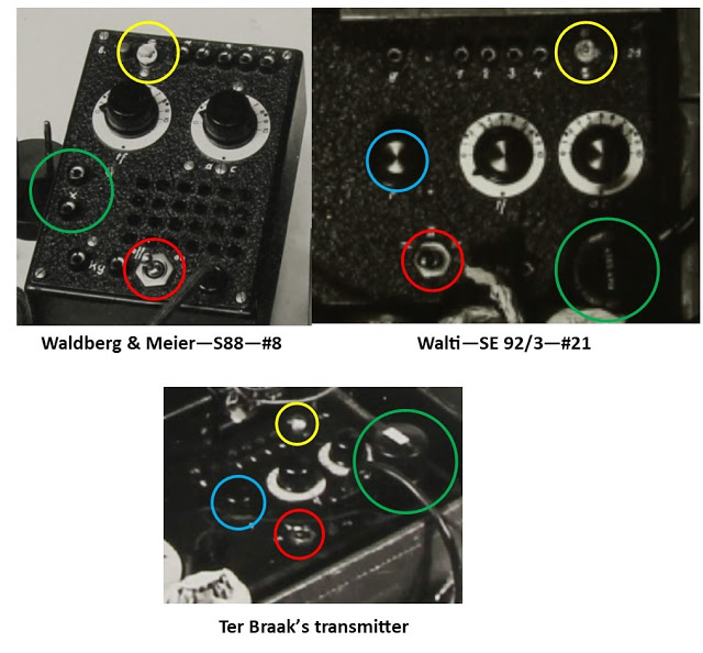
Green = crystal sockets, yellow = tuning bulb, red = on/off switch (S88/5) or switch to move between transmitter and receiver (SE 92/3), blue = receiver’s regeneration dial.
Images – minus the coloured circles – from NA KV 2 files.
Comparison of various elements of the S88/5 and SE 92/3 transmitters from Waldberg & Meier (S88/5) and Walti and Ter Braak (SE 92/3). Green = crystal sockets, yellow = tuning bulb, red = on/off switch (S88/5) or switch to move between transmitter and receiver (SE 92/3), blue = receiver’s regeneration dial. Images – minus the coloured circles – from NA KV 2 files.
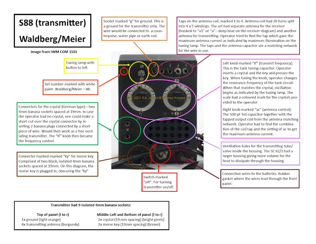
S88/5 Transmitter
I chose to use the S88/5 transmitter picture from the IWM (COM 1501) as my base image. It has the best perspective of the S88/5 and it was easy to identify and label all of the different components of the front panel. This particular S88/5 is #8 and belonged to Waldberg and Meier who had landed on the coast of Kent in early September 1940. Kieboom and Pons also had an S88/5 but their transmitter is much less photographed. TATE also had an S88 which looks identical to that of Waldberg & Meier, but photographs of it were taken at an oblique angle.
I’ve circled the various components of the front panel of the S88/5 and coloured coded the circles and the accompanying descriptions. The colour coding will match the various components on the SE92/3 with its single housing containing both transmitter and receiver. Thomas was a valuable source of information and much of the text in the boxes comes from him. I realize that the images below may be far too small for readability so have tucked them into a Google Photo Album for increased legibility.
E88 Receiver
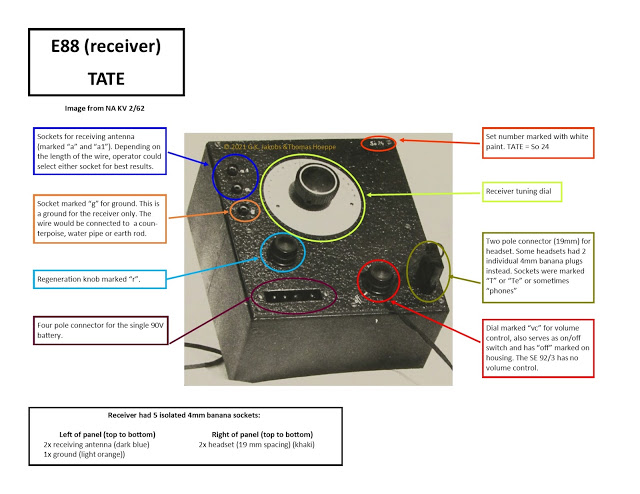
Next up we have an E88 receiver, in this case the one belonging to double-agent TATE. He appears to have been the only agent sent to England with an SE 88/5 transmitter/receiver combination. Waldberg, Meier, Kieboom and Pons did not have receivers with them when they landed in the UK.
Technically, this was the standard E75 receiver which was used in a number of other sets (SE 85/14 and SE90/40). The receiver used in the SE 88/5 set had black textured paint and hand-painted white lettering, unlike the E85 or E90. Thomas suggested that I refer to this receiver as the E88 receiver and I am happy to defer to his expertise.
The colour-coded circles and descriptions match the same components on the following SE92/3 transmitter/receiver.
SE 92/3 Transmitter / Receiver
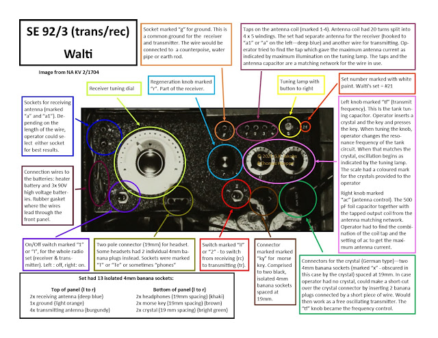
Finally, we have combined transmitter/receiver housed in a single box. In this case, I am using a photograph of Walti’s set as the head-on perspective is perfect for labelling and identifying each dial, knob and socket.
Since this single diagram contains all of the components of both transmitter and receiver, it’s a bit busy but all of the colour-coding of the various components matches those of the two diagrams above – e.g. the tuning lamp on the transmitter is always yellow and the receiver tuning dial is always lime green.
If one examines the diagrams in detail, one can see that several components have moved around from the SE 885 to the SE 92/3. The crystal socket (bright green), for example, is in a different location on the S88/5 transmitter. The receiver regeneration knob (light blue) almost appears to be part of the transmitter components on the SE 92/3.
Confusion Perpetuated
One of the reasons why I wanted to create these diagrams is because of confusion that arises from various photographs and displays of spy sets.
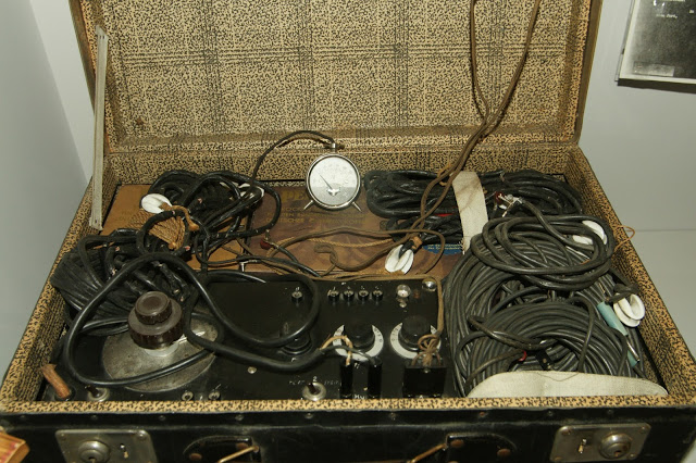
Let’s start with the suitcase transmitter on display at the Imperial War Museum. If we compare it to the above diagrams, we can see that it is an SE 92/3. But if one looks closely, one can see that the headphones cord (the brown cord) has been plugged into the crystal socket. It is unclear what is plugged into the key socket although the thickness of the cord suggests it might, correctly, be the actual Morse key.
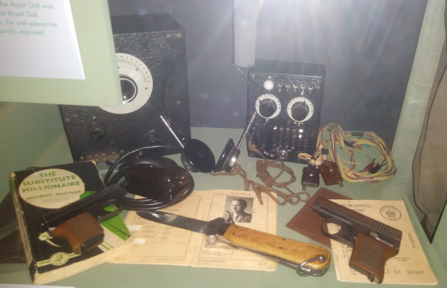
The display in Edinburgh is not much better. One can see that the headphones (brown cord) are plugged into the crystal socket. And it looks as if the Morse key might be plugged into the headphones socket of the receiver.
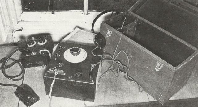
The SE 88/5 radio belongs to TATE.
This image of TATE’s set below, however (After the Battle, Volume 11), appears to have everything plugged in correctly: crystal, Morse key, headphones, receiver batteries.
At this point, I’m toying with the idea of sending the SE 92/3 diagram to the Imperial War Museum. They could tweak their displays for accuracy, both for the suitcase transmitter/receiver and for the S88/5 of Waldberg and Meier (which they have listed as belong to Kieboom).
Many thanks to Thomas (as always) for guiding me through the finer details of these wireless radios.
Sources
National Archives – KV 2/62 (TATE), KV 2/1704 (Walti)
Imperial War Museum – photos of the S88/5 of Waldberg and Meier
After the Battle – volume 11
